

Interference of Light
What is Huygens wave
theory principle?
Huygen’s wave theory gives an idea about the nature of light. According to this theory, light is a sort of disturbance. The particles of the medium vibrate in a direction at right angle to the direction of propagation of disturbance. The process is called wave motion.
Considering light to be a wave-motion following properties of light could be explained:
(a) Rectilinear propagation of Diffraction (f) Polarization
Huygen’s Principle
light (b) Reflection (c) Refraction (d) Interference (e)

Wave front – The envelope of all wavelets in the same phase- having received light from sources in the same phase at the same time is called a wave front.
Wave normal – The normal at any point drawn outward on a wave front is called the wave normal. Further propagation of light occurs along the wave normal. In isotropic media the wave normal coincides with the 'ray of light'.
What are the sources
of spherical and cylindrical wavefront?
Spherical, cylindrical and plane wave fronts
The wave fronts from a point of the primary source are spherical wave fronts. The wave fronts from the line primary source are cylindrical wave fronts.
How can we construct new wavefront?
Construction of Wave Front
Wave-front of a wave, at any instant, is defined as the locus of all the particles in the medium which are being disturbed at the same instant of time and are in the same phase of vibration.

The answer is that Huygen’s principle gives us the guide lines to do so. Steps to be followed, in this process, are called the basic postulates of the principle and they are stated below.
a) Consider all the points on a primary wave-front (of instant t) to be the sources of light, which emit disturbances known as secondary disturbance.
b) Tangent envelope to all the secondary wave-lets gives the position of a new wave-front.
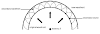
Consider a point source S. Light emitted by S travels in all directions. Let AB be a section of the position of wave-front, at any instant of time, t as shown in figure. The
secondary disturbances emitted by all the points on AB are shown by dotted circles. A1
B1 and A2 B2 are the two tangent envelopes touching all these secondary disturbances.
According to Stoke’s law, the intensity at each point of the secondary wave is
proportional to (1 + cos θ). Here θ is angle between normal and central line.
For backward wave-front ‘A2 B2’ (shown dotted), θ = π
So, cos θ = cos π = - 1
Thus, intensity at any point on backward wave = k (1 + cos π) = k (1-1) = 0.
Therefore back wave-front does not exist.
Hence, ‘A1B1’ which is the forward wave-front gives the position of wave-front at the later instant.
Every point on a wave-front may be considered a source of secondary spherical
wavelets which spread out in th forward direction at the speed of light. The new wave-front
is the tangential surface to all of these secondary wavelets.
What are the two types of wave fronts?
Straight wave front
Huygens's principle applied to a straight wave front. Each point on the wave front emits a semicircular wavelet that moves a distance s = v t.
The new wavefront is a line tangent to the wavelets.

Huygens Refraction
Huygens principle applied to a straight wavefront traveling from one medium to another where its speed is less. The ray bends toward the perpendicular, since the wavelets have a lower speed in the second medium.
Huygens Reflection
Huygens's principle applied to a straight wave front striking a mirror. The wavelets shown were emitted as each point on the wave front struck the mirror. The tangent to these wavelets shows that the new wave front has been reflected at an angle equal to the incident angle. The direction of propagation is perpendicular to the wave front, as shown by the downward-pointing arrows.
What is interference in physics examples?
Interference
Two waves are said to interfere if they cross one another at any point. It is found that the resultant amplitude and consequently in the intensity of light gets modified when tow light beams interfere. This modification of intensity obtained by the superposition of two or more beams of light is called Interference.
In order to find out resultant amplitude when two waves interfere we make use of the principle of superposition.
What is the principle of superposition with an example?
Principle of Superposition:
Principle of superposition states that the resultant displacement at any point at any instant may be found by adding the instantaneous displacement that would be produced at the point by the individual wave trains if each were present alone. In the case of light waves, by displacement we mean the magnitude of electric field or magnetic field intensity.
Let y1 and y2 be that displacement of two individual waves traveling in the same direction. On superposition of these two waves at a point, that resultant displacement is given by,
𝑅 = 𝑦1 + 𝑦2 (1)
Coherence: Coherence means that two or more electromagnetic waves are in a fixed predictable phase relationship to each other.
There are two independent concepts of coherence namely temporal coherence and spatial coherence.
Temporal coherence: This refers to the correlation between the field at a point at time t1 [E(x,y,z,t1)] and the field at the same point at a later time t2 [E(x,y,z,t2)]. If the phase difference between the points is constant during the period, the wave is said to have temporal coherence.
Spatial coherence: The waves at different points in space are said to be space coherent if they preserve a constant phase difference over anytime t.
Time coherence is a character of a single beam of light whereas space coherence concerns the relationship between two separate beams of light. Interference is a manifestation of coherence.
Interference can be produced by two ways:
i. Division of wavefront: by reflection, refraction or diffraction.
e.g. Young's double slit experiment
ii. Division of amplitude: by parallel reflection or refraction.
e.g. Newton's rings.
Young’s Double Slit Experiment
Thomas Young (1773–1829) an English physicist and physician demonstrated wave character of light by demonstrating optical interference with his double-slit experiment.
In Young’s experiment, sunlight was passed through a pinhole on a board. The emerging beam fell on two pinholes on a second board. The light emanating from the two pinholes then fell on a screen where a pattern of bright and dark spots was observed. This pattern, called fringes, can only be explained through interference, a wave phenomenon.
When light passes through narrow slits, the slits act as sources of coherent waves and light spreads out as semicircular waves, as shown in Figure. Pure constructive interference occurs where the waves are crest to crest or trough to trough. Pure destructive interference occurs where they are crest to trough.
The regions of constructive and destructive interference move out from the slits at well-defined angles to the original beam. These angles depend on wavelength and the distance between the slits, as we shall see below.

Figure: Double slits produce
two coherent sources
of waves that interfere. (a) Light spreads
out (diffracts) from each slit, because
the slits are narrow. These waves overlap
and interfere constructively (bright lines) and destructively (dark regions). We can only see this if the light falls
onto a screen and is scattered into our eyes.
(a) When light that has passed through
double slits falls
on a screen, we see a pattern
such as this.
Conditions for Interference
Observable interference can take place if the following conditions are fulfilled:
a) The two sources should emit, continuously, waves of some wave-length or frequency. While deriving conditions for maxima and minima, we have taken intensity of both the waves to be same.
(b) The amplitudes of the two waves should be either or nearly equal. A good contrast between a maxima and minima can only be obtained if the amplitudes of two waves are equal or nearly equal.
(c) The two sources should be narrow. A broader source can be supposed to be a combination of a number of narrow sources assembled side-by-side. Interference patterns due to these narrow sources may overlap each other.
between the two sources. So, interference pattern will be more clear and distant if d is small.
(e) The two sources should be coherent one.

According to Huygens principle, wavelets from A and B spread out and overlapping takes place to the right side of AB. When a screen XY is placed at a distance of about 1 meter from the slits, equally spaced alternate bright and dark fringes appear on the screen. These are called interference fringes or bands. Using an eyepiece the fringes can be seen directly. At P on the screen, waves from A and B travel equal distances and arrive in phase. These two waves constructively interfere and bright fringe is observed at P. This is called central bright fringe.
When one of the slits is covered, the fringes disappear and there is uniform illumination on the screen. This shows clearly that the bands are due to interference.
Let d be the distance between two coherent sources A and B of wavelength λ. A screen XY is placed parallel to AB at a distance D from the coherent sources. C is the midpoint of AB. O is a point on the screen equidistant from A and B. P is a point at a distance x from O, as shown in Fig 5.17. Waves from A and B meet at P in phase or out of phase depending upon the path difference between two waves
Draw AM perpendicular to BP The path difference δ = BP – AP AP = MP
δ = BP – AP = BP – MP = BM
In right angled triangle ABM, BM = d sin θ If θ is small, sin θ = θ The path difference δ = θ d
In right angled triangle COP, tan θ = OP/CO = x/D For small values of θ, tan θ = θ
D
|
𝑛+1 − 𝑥𝑛 = (𝑑)
Bandwidth, 𝛽 = (𝐷) 𝜆
𝑑
𝑘
+ 1
𝜆
− (𝑑)
𝑘 𝜆
= (𝑑) 𝜆
Similarly, it can be proved that the distance between two consecutive dark bands is also equal to (𝐷) 𝜆. Since bright and dark fringes are of same width, they are equi-spaced on
𝑑
either side of central maximum.
What are the necessary conditions for obtaining interference fringes?
Condition for obtaining clear and broad interference bands:
i. The screen should be as far away from the source as possible.
ii. The wavelength of light used must be larger.
iii. The two coherent sources must be as close as possible.
What is interference in thin film mainly?
Interference in thin films by reflected light
A transparent thin film of thickness t and refractive index μ is surrounded by air as shown in the figure.
Let a monochromatic wave of wavelength λ is incident at A on the top surface of the film at an angle i. Part of the ray is reflected along AB and part of it is refracted along AC. At bottom surface at point C the ray is reflected and further refracted at point D along DE.
Thus the reflected rays AB and DE are coherent and produce bright and dark interference fringes depending on the path difference.
DN is a perpendicular drawn to AB and N is the foot of the perpendicular. Beyond N and D both the rays travel common path.

The path difference between the rays is given by,
δ = path ACD in film – path AN in air
thus, ð = 𝜇(AC + CD) − AN
![]()
![]() From
the ∆ ACM, cos 𝑟
= 𝐶𝑀 =
From
the ∆ ACM, cos 𝑟
= 𝐶𝑀 =
Æ𝐶
𝑡 Æ𝐶
(since, CM = t )
![]() or 𝐴𝐶 = 𝑡
or 𝐴𝐶 = 𝑡
Cos 𝑟
![]() Similarly, from the ∆ DCM, 𝐶𝐷 = 𝑡
Similarly, from the ∆ DCM, 𝐶𝐷 = 𝑡
Cos𝑟
![]() Thus, 𝐴𝐶 +
𝐶𝐷 = 2𝑡
Thus, 𝐴𝐶 +
𝐶𝐷 = 2𝑡
Cos 𝑟
tan 𝑟
= 𝐴𝑀 = 𝐴𝑀
![]()
![]()
𝐶𝑀 𝑡
![]() or 𝐴𝑀 = 𝑡 tan 𝑟 = 𝑡 sin 𝑟
or 𝐴𝑀 = 𝑡 tan 𝑟 = 𝑡 sin 𝑟
Cos 𝑟
![]() we know that, 𝜇 = sini sin 𝑟
we know that, 𝜇 = sini sin 𝑟
or sin
i = 𝜇 sin 𝑟
![]() From
the ∆ ACM, sin i = Æ𝑁
From
the ∆ ACM, sin i = Æ𝑁
Æ𝐷
![]()
![]() or 𝐴𝑁 = 𝐴𝐷 sin i = 2(𝐴𝑀)𝜇 sin 𝑟 = 2𝑡 sin 𝑟 𝜇 sin 𝑟 = 2𝜇𝑡 𝑠i𝑛2𝑟
or 𝐴𝑁 = 𝐴𝐷 sin i = 2(𝐴𝑀)𝜇 sin 𝑟 = 2𝑡 sin 𝑟 𝜇 sin 𝑟 = 2𝜇𝑡 𝑠i𝑛2𝑟
Therefore,
2𝜇𝑡
𝑠i𝑘2𝑟
Cos 𝑟
![]()
![]() (1 − 𝑠i𝑘2𝑟)
(1 − 𝑠i𝑘2𝑟)
Cos 𝑟
𝑐o𝑠2𝑟
![]()
![]() ð = cos 𝑟 −
2𝜇𝑡 cos 𝑟
= 2𝜇𝑡
ð = cos 𝑟 −
2𝜇𝑡 cos 𝑟
= 2𝜇𝑡
or ð = 2𝜇𝑡
cos 𝑟 For normal incidence, 𝑟 = 00 Hence, ð = 2𝜇𝑡
cos 𝑟 = 2𝜇𝑡 cos 𝑟 =
2𝜇𝑡 cos 𝑟
It should be noted that, the ray AB is reflected from denser medium and thus a phase
![]() difference of p or a path difference of
difference of p or a path difference of
2
is introduced in the path. But the ray reflected from
the bottom of the film has no phase change. Therefore the path difference is now given by
![]() ð = 2𝜇𝑡 cos 𝑟 −
ð = 2𝜇𝑡 cos 𝑟 −
2
Case i: Condition for maxima.
![]() For constructive interference, the path difference should be equal to the even multiple of .
For constructive interference, the path difference should be equal to the even multiple of .
2
Thus,
![]()
![]() 2𝜇𝑡 cos 𝑟 − = 2𝑚
2𝜇𝑡 cos 𝑟 − = 2𝑚
where m = 1,2,3……etc
2 2
![]() or 2𝜇𝑡 cos 𝑟 = (2𝑚 + 1) 2
or 2𝜇𝑡 cos 𝑟 = (2𝑚 + 1) 2
This is the condition for maxima. The film appears bright in this case.
Case ii: Condition for minima.
![]() For destructive interference, the path difference should be equal to the odd multiple of .
For destructive interference, the path difference should be equal to the odd multiple of .
2
Thus,
![]()
![]() 2𝜇𝑡 cos 𝑟 − = (2𝑚 − 1)
2𝜇𝑡 cos 𝑟 − = (2𝑚 − 1)
where m = 0,1,2,3……etc
2 2
or 2𝜇𝑡 cos 𝑟 = 2𝑚𝜆
This is the condition for minima. The film appears dark in this case.
What is the Newton's ring?
Newton's rings
When a plano-convex lens with its convex surface is placed on a plane glass plate, an air film of gradually increasing thickness is formed between the two. If monochromatic light is incident normally on the lens then alternate dark and bright concentric circular rings are viewed in the reflected lights. These rings are called Newton’s rings.
The fringes are
circular because the air film has a circular symmetry. The central fringe is dark because the thickness of the air film at
the point of
contact is zero. Theory of Newton's
rings:
Newton's rings are formed due to interference between light waves reflected from the top and bottom surfaces of air film between the glass plate and the lens as shown in the figure.

![]() The path difference between the rays 1 and 2 is given by Γ = 2𝜇𝑑 cos 𝑟 +
The path difference between the rays 1 and 2 is given by Γ = 2𝜇𝑑 cos 𝑟 +
2
(2)
since r = 0, m=1; then
![]() Γ = 2𝑑
+
Γ = 2𝑑
+
2
![]() At the point of contact d = 0, and Γ = . Hence the central spot is dark.
At the point of contact d = 0, and Γ = . Hence the central spot is dark.
2
(3)
The condition for bright fringe is
![]() Γ = 2𝑑 + = 𝑘l (4)
Γ = 2𝑑 + = 𝑘l (4)
2
or
![]() 2𝑑 = (2𝑘 − 1)
2𝑑 = (2𝑘 − 1)
2
(5)
where 𝑘 = 1, 2, 3, … …
The condition for dark fringe is,
![]()
![]() Γ = 2𝑑 + = (2𝑘 + 1)
Γ = 2𝑑 + = (2𝑘 + 1)
(6)
2 2
or
2𝑑 = 𝑘l
(7)
were 𝑘 = 0, 1, 2, 3, ….
To calculate the diameter of the Rings:
Let LOL’ be the lens placed
on the glass plate AB as shown in the figure. The curved surface
is part of the spherical
surface with the centre at C. Let R be the radius of curvature of lens. Let r be the radius of Newton's ring corresponding to constant film thickness d.

From the property of the circle,
𝑁𝑃 × 𝑁𝑄 = 𝑁𝑂 × 𝑁𝐷
𝑟 × 𝑟 = 𝑑(2𝑅 − 𝑑) =
2𝑅𝑑 − 𝑑2
𝑟2 ≅ 2𝑅𝑑 (8)
![]() 𝑑 = 𝑟2
𝑑 = 𝑟2
2𝑅
Therefore the condition for the bright fringe is given by,
![]()
![]() 2𝑑 = 2 𝑟2 = (2𝑘 − 1)
2𝑑 = 2 𝑟2 = (2𝑘 − 1)
(9)
(10)
2𝑅 2
𝑟2 = (2𝑛−1) 𝜆𝑅 (11)
2
![]() Since the diameter is 𝐷 = 2𝑟 or = 𝐷 , we get
Since the diameter is 𝐷 = 2𝑟 or = 𝐷 , we get
2
![]()
![]() 𝑟2 = 𝐷2 = (2𝑛−1) 𝜆𝑅 (12)
𝑟2 = 𝐷2 = (2𝑛−1) 𝜆𝑅 (12)
4 2
𝐷𝑛 = √2𝑘 − 1 √2𝜆𝑅 (13)
Similarly, for dark fringe,
![]() 2𝑑 = 2 𝑟2 = 𝑘𝜆 (14)
2𝑑 = 2 𝑟2 = 𝑘𝜆 (14)
2𝑅
𝑟2 = 𝑘𝜆𝑅 (15)
![]() Since the diameter is 𝐷 = 2𝑟 or = 𝐷 , we get
Since the diameter is 𝐷 = 2𝑟 or = 𝐷 , we get
2
![]() 𝑟2 = 𝐷2 = 𝑘𝜆𝑅
𝑟2 = 𝐷2 = 𝑘𝜆𝑅
4
𝐷𝑛 = 2√𝑘𝜆𝑅
What is the method of determination of wavelength?
Determination of wavelength of light source:
The experimental arrangement is as shown in the figure. The plano- convex lens (L) of large radius of curvature (R) is placed with its convex surface on a plane glass plate G. The lens makes the contact with the plate at O. The monochromatic light from the source falls on a plain glass plate B held at an angle of 45°. The glass plate B reflects normally a part of the incident light towards the air film enclosed by the lens L and glass plate G and gets reflected backward. These reflected rays interfere and give rise to an interference pattern in the form of circular rings which can be seen by the microscope M.

By measuring the diameter of the Newton's rings, the wavelength of light (λ) can be determined by the following formula.
𝐷2 − 𝐷2
where Dn = diameter of nth dark ring
𝜆 =
𝑛+𝑝 𝑛
![]()
4𝑝𝑅
Dn+p = diameter of (n+p)th dark ring
R = Radius of curvature of Plano-convex lens
What is Huygens wave theory principle?
What are the sources
of spherical and cylindrical wavefront?
What are the two types
of wavefronts?
What is interference
in physics examples?
What is the principle
of superposition with an example?
What is the principle of superposition 12th
class?
What is the principle of superposition with an
example?
What is the principle of superposition Mcq?
What is the principle
of superposition derivation Class 11?
What is bright fringes and dark fringes?
What causes bright fringes?
What is the formula for bright fringe?
What are the bright
fringes in interference?
What are the necessary
conditions for obtaining interference fringes?
What are the conditions for clear interference
pattern?
What are the necessary conditions for
obtaining interference fringes?
What are the two conditions to obtain sustained
interference?
What is the condition
for obtaining interference rings with good contrast?
What is an example of
interference of light in a thin film?
Why an excessively
thin film appears dark when observed in reflected light?
What is interference
in thin film mainly?
What is the Newton's
ring? What is the method of determination of wavelength?
How do you measure the wavelength of light
experiment?
How can you determine
the wavelength of a given light source using diffraction grating?

.jpeg)


.jpeg)


0 Comments